


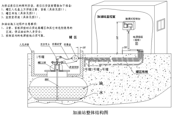
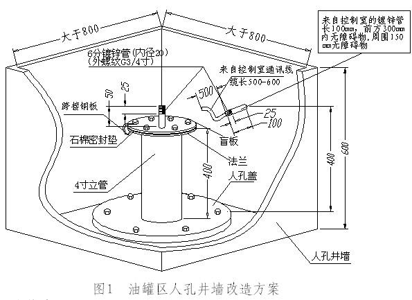
First, the tank area riser transformation:
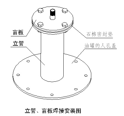
◆4 inch riser processing and welding: the riser must be welded vertically to the manhole cover, and the inside of the manhole cover should not exceed 50mm. The inner wall of the riser is smooth and free of welding slag;
◆The right side of the riser welding position should be free of obstacles to the bottom of the tank, otherwise it will easily cause the float to move poorly;
◆The exposed length of the galvanized threading pipe in the manhole wall is 100mm, the external thread (G3/4) is 25mm long, the communication cable is exposed 500-600mm (as shown in Figure 1), and the surrounding area is free of obstacles within 150mm. No obstacles within 300mm in front;
◆The center of the blind plate shall be welded with a length of 50mm galvanized pipe and the outer wire pipe thread (G3/4) with a length of 25mm;
◆Asbestos pad seal is added between the flange and the blind plate, and the copper bar is used for bridging;
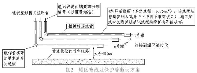
Second, wiring transformation: (Figure 2)
◆The probe of each tank needs a separate communication cable to connect to the touch console. The communication cables of all probes must be worn in the galvanized pipe (the elbow connection is required at the bend). Ensure that the insulation sheath of the communication cable is not damaged;
◆Wiring number: The communication cable requirement number of each tank from the manhole to the touch room of the monitoring room. The number is based on the tank number, which is convenient for distinguishing and installing;
◆The liquid level meter communication can't be worn in the same tube with other lines, and the distance from other lines is more than 400mm.。

Third, the tank monitoring room transformation program:
◆ Touching console fixed position: As shown in Figure 3, two holes with diameter Φ8 and depth of 60mm are drilled with impact drill, TCC-1 hole spacing is 270mm, TCM-2 hole spacing is 250mm. Expansion tube size Φ8×48 two pieces, pan head wood screws ST4×60 two pieces;
◆Indoor wiring: from the irrigation area to the monitoring room, the four-core shielded cable to the touch-type console is only below the horizontal or vertical line, the corner is connected with elbows, all the cables are in the line slot, no bare lines The two ends of the cable slot should be sealed (including all grounding wires), and the cable directly under the console is reserved for about 0.5 meters;
◆ Grounding wire: Touch type console and power socket (plug strip) require reliable grounding, grounding resistance is less than 1Ω, grounding wire is multi-strand copper cord, diameter requirement is ≥4mm2, and the distance between the plug (power) and the console is the farthest. Must not exceed 1.5 meters;
◆ Threading pipe: The threading pipe is more than 200mm away from the indoor floor, and the indoor threading pipe port needs to be sealed with explosion-proof mud;
◆Outdoor explosion-proof electric bell wiring: The four-core shielded cable passes through the cable trough from the console of the monitoring room to the installation of the explosion-proof electric bell in the tank area. The cable for the installation of the explosion-proof electric bell is reserved for 2 meters, and the cable below the console is reserved for about 0.5 meters. .
Construction requirements:
1. The riser welding position is as close as possible to the tank diameter position;
2. The riser is perpendicular to the oil level of the tank;
3. The inner wall of the riser is smooth and has no welding slag;
4. No obstacles in the vertical area below the riser.
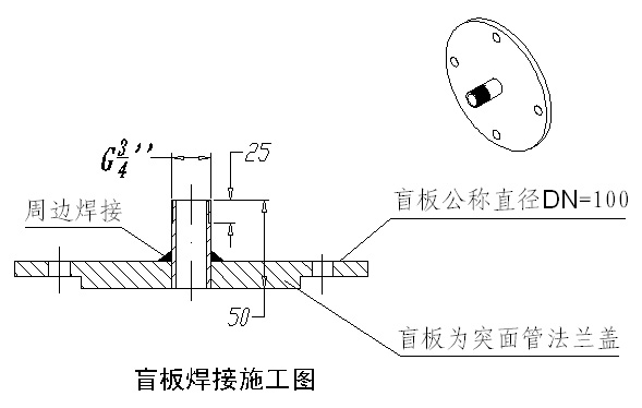
Blind board processing requirements:
1. The size of the mounting hole of the blind plate is matched with the pipe flange;
2. Smooth welding, no welding slag;
3. Surface spray treatment (anti-rust paint or silver powder).
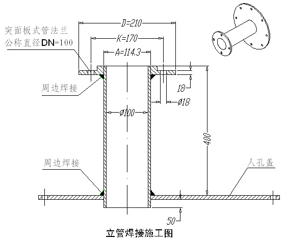
Riser processing requirements:
1. The outer diameter of the riser and the inner diameter of the flange should not be too large;
2. The riser welding position is as close as possible to the tank diameter position;
3. The riser is perpendicular to the oil level of the tank;
4. The inner and outer walls of the riser are smooth and have no welding slag;
5. No obstacles in the vertical area directly below the riser;
6. Surface spray treatment (anti-rust paint or silver powder).